Post by: The Gonz on October 13, 2018, 06:28:31
:link: 1 Set T20 W21W 7440 42SMD Switchback Car Auto Dual Color LED Turn Signal Lights | eBay (https://www.ebay.com.au/itm/1-Set-T20-W21W-7440-42SMD-Switchback-Car-Auto-Dual-Color-LED-Turn-Signal-Lights/132384379783?ssPageName=STRK%3AMEBIDX%3AIT&_trksid=p2060353.m2749.l2649)
These bad boys are in and doing their thang.
For each side, I removed the front light cluster using the 3 10mm bolts, then twisted and removed the turn globe bases. These new bases were smaller but I reused the grey rubber washer from the original base and then fashioned a clamp to keep the new base centred and airtight using spring tensioned coathanger wire fixed to a bar of coathanger wire slipped through the full length of what looks like a narrow shaft used to adjust beam angle from above using a long screwdriver when fitted.
I now have all the normal turn, hazard and lock indications in LED form but the new feature of DRL I have left until I determine the best source for its voltage. ACC is generally assumed but since I'm in the engine bay I'd rather pick off something that appears once the engine is running.
Any suggestions?
Post by: CraigB on October 13, 2018, 06:39:37
Post by: The Gonz on October 13, 2018, 07:00:27
Without getting into the legalistics, I prefer them to go off when beams are on, so I'll get a relay, which will most likely resolve my problem of finding the right source. :lol:
Post by: CraigB on October 13, 2018, 07:06:33
Post by: tla on October 13, 2018, 07:51:29
The only downside is that the DRL remains on for 10+ seconds after the engine is turned off, while the voltage is still above 13V.
I'm sure you can DIY a similar voltage detection mechanism to control a standard relay.
Post by: The Gonz on October 13, 2018, 13:06:08
Post by: The Gonz on October 14, 2018, 10:28:08
Does the existing relay switching the parkers include a normally closed contact? If so, I shouldn't be needing to add another relay at all. Does anyone have a spec on said relay?
Post by: tla on October 14, 2018, 21:26:31
(click to show/hide)
Looking forward to photos of your DRLs in action. :goodjob2:
Post by: The Gonz on October 15, 2018, 20:08:50
Post by: tla on October 15, 2018, 21:13:18
(click to show/hide)
Post by: The Gonz on October 16, 2018, 06:02:12
Post by: The Gonz on October 31, 2018, 07:19:00
Post by: CraigB on October 31, 2018, 08:39:50
Post by: The Gonz on October 31, 2018, 10:31:29
Post by: The Gonz on November 17, 2018, 07:06:23
The half not solved is trying to get voltage out of HL LO LH or HL LO RH (16 and 17) for a similar voltage.
The idea is to find the low beam headlamp voltage supply at a fuse so I can finish wiring my newly arrived 5-pin changeover relay's Normally Closed contacts (30 as the DRL feed and 87a getting 15's power) to open when coil contact 86 has headlamp power applied, with 85 to ground.
Hence I'll have the DRLs shut off when headlamps are turned on, but be on when the ignition is on. So, any better fuse I can use for headlamp power?
Post by: tw2005 on November 17, 2018, 20:43:07
Below is a schematic of the relevant circuit for the parkers on the FD. It looks like it shares the tail lamp relay and fuse. Looks like the relay is normally open.@tla(click to show/hide)
Looking forward to photos of your DRLs in action. :goodjob2:
Mate, just checking what vehicle these schematics are for. GD or FD? To my knowledge there is no FD 3 door
Post by: tla on November 17, 2018, 20:50:24
Post by: tw2005 on November 17, 2018, 21:05:49
@The Gonz
From what I can see there may have been a DRL feature built into the BCM that ran the headlamp Lo beam
There's no discrete DRL module for FD that I can find.
This is what I have for the circuits, may not be exact for our market
(https://preview.ibb.co/d5ETpf/FD-lamps-1.jpg) (https://ibb.co/eNP6aL)
(https://preview.ibb.co/fsVevL/FD-lamps-2-1.jpg) (https://ibb.co/gYoA20)
(https://preview.ibb.co/mEf19f/drl1.jpg) (https://ibb.co/kg4Tpf)
(https://preview.ibb.co/ktVq20/drl2.jpg) (https://ibb.co/i5TM9f)
Post by: The Gonz on November 17, 2018, 21:19:46
Post by: tw2005 on November 17, 2018, 21:35:12
It doesn't quite sound like English to me and may need some digesting. For starters, I'll have to locate the BCM! Thanks for the effort and info. :victory:In behind centre fascia, will have to be removed, and it's tight in there, the antenna will give it away
I think there's 3 plugs and a lot of pins :mrgreen:
Post by: The Gonz on November 17, 2018, 21:45:39
I'm thinking I'll keep probing the engine bay fuse box. If nothing there, I'll pick it off the cluster connector. :sweating:
Post by: The Gonz on November 20, 2018, 06:47:00
I picked the IGN feed off the high side of fuse 15 and hooked it up to the Normally Closed pin of the relay, then hooked up the DRL supply line to the switch Common relay pin.
Without going any further, since I was keen on seeing the DRLs work, I turned the key to IGN and ...
WOW! Those suckers are bright!
To test the relay's job of turning them off when the headlights go on would mean hooking up a ground for the low side of the relay coil, although I already had the headlight pin in the cluster connected to the coil's high side.
So I decided to test the interaction of DRL and turn indicator for now. eBay tells me they are white until turning, then off/amber, then back to white.
Well, the off bit isn't really happening to my satisfaction, so it's back to non-DRL blinking for now until I investigate further. :needspecscleaning:
It may be that the desired behaviour is only possible via relay anyway! :crazy1:
Post by: CraigB on November 20, 2018, 07:03:34
WOW! Those suckers are bright!Must I do the reminding :whistler: :ttiuwp:
Post by: tw2005 on November 20, 2018, 07:32:55
So ... :confused:DOn't forget some pics, I'm a visual person :scared:
I picked the IGN feed off the high side of fuse 15 and hooked it up to the Normally Closed pin of the relay, then hooked up the DRL supply line to the switch Common relay pin.
Without going any further, since I was keen on seeing the DRLs work, I turned the key to IGN and ...
WOW! Those suckers are bright!
To test the relay's job of turning them off when the headlights go on would mean hooking up a ground for the low side of the relay coil, although I already had the headlight pin in the cluster connected to the coil's high side.
So I decided to test the interaction of DRL and turn indicator for now. eBay tells me they are white until turning, then off/amber, then back to white.
Well, the off bit isn't really happening to my satisfaction, so it's back to non-DRL blinking for now until I investigate further. :needspecscleaning:
It may be that the desired behaviour is only possible via relay anyway! :crazy1:
Post by: The Gonz on November 20, 2018, 07:39:55
I guess I was hoping the logic to switch between DRL and Turn Indicator was all built into the base but what I saw has me thinking there's nothing there but the wiring to deliver 'dumb' current.
The next step will need to be sourcing yet another relay to pick off the turn signal, preferably before it becomes intermittent, to switch the DRL feed off while the blinker operates. I can easily pick the intermittent voltage off the cluster where I already have but that would be sub-optimal.
So ... any idea whether a steady voltage exists anywhere in the engine bay to run the blinkers? :Dunno:
Post by: The Gonz on November 22, 2018, 00:03:29
:link: Automotive Relay Guide | 12 Volt Planet (https://www.12voltplanet.co.uk/relay-guide.html)
So I've ordered 2 more of the same relay I've used to inhibit the DRLs during lights on. They will be fitted 1 each behind the indicator wiring to inhibit the DRL during the amber voltage. It won't give me black-amber back to white but will give me white-amber back to white, and I can live with that. I promise video when the new relays arrive. :victory:
And yes, no surprise I have my sights set on a new eBay mod, this time a solution looking for a problem: :link: 1PCS TEC1-12706 Heatsink Thermoelectric Cooler Cooling Peltier Plate Module | eBay (https://www.ebay.com.au/itm/1PCS-TEC1-12706-Heatsink-Thermoelectric-Cooler-Cooling-Peltier-Plate-Module/273337351636?hash=item3fa42cfdd4:g:xvoAAOSwkxRasyQq&redirect=mobile)
Post by: tw2005 on November 22, 2018, 08:25:16
:faint:
Post by: The Gonz on December 17, 2018, 02:26:57
Using a 5 pin relay, I tapped fuse 15's high side to feed IGN to the DRL function of my blinkers along with a tap of the parking lamp voltage out of the cluster connector such that with IGN on the DRLs are on but off with headlights on.
The other two 5 pin relays tap the turn signai out of the cluster connectors as well as the DRL feed from the first relay in order to behave normally with DRL but to blink the DRL as a turn indication when on.
The 3 states of turn, DRL and headlight behaviour have been photographed and uploaded to the Facebook site: :link: i30 Owners Club Public Group | Facebook (https://facebook.com/groups/298612675352?multi_permalinks=10156659984495353¬if_t=feedback_reaction_generic¬if_id=1545016662129905&ref=m_notif)
Post by: The Gonz on December 22, 2018, 09:57:48
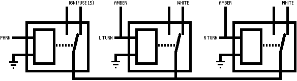
You should be able to trace the behaviour of the DRLs and blinkers by following the logic. Energising the relays switches them from where they are currently at rest (normally closed) to an open state (the normally open contacts are unused).
Post by: tw2005 on December 26, 2018, 10:17:56
For those keen on emulating the switchback implementation, here's the schematic for the relays I used:Hi, The relays appear to do what you intend and back emf was on my mine too but since the diodes did nothing then not the case I would think.
You should be able to trace the behaviour of the DRLs and blinkers by following the logic. Energising the relays switches them from where they are currently at rest (normally closed) to an open state (the normally open contacts are unused).
what happens when hazards are selected?
Post by: The Gonz on December 27, 2018, 01:40:12
Post by: The Gonz on December 28, 2018, 02:59:44
Post by: The Gonz on December 28, 2018, 03:34:24
Thanks in advance for any clues. :goodjob:
Post by: The Gonz on December 28, 2018, 04:40:38
:thanx:
Post by: The Gonz on December 28, 2018, 05:36:29
The drama continues.
Removal of driver’s crash pad (2 screws visible) and driver’s crash pad reinforcing panel (5 bolts) is required to get to even see the flasher unit!
Why couldn’t this be accessible through a panel door like the fuse box, or a hole like the OBD? :crazy1:
Eventually I’ll gather the courage to yank the bits out (with more space and direct light) and replace the flasher with an electronic one that won’t hyper flash anyway, so I can dispense with the 6 Ohm load resistors as well.
Post by: The Gonz on December 28, 2018, 06:13:52
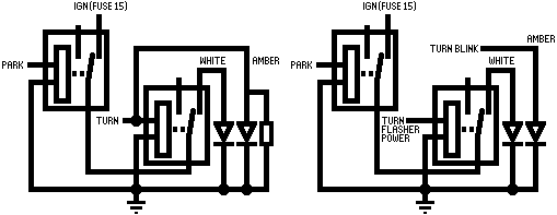
OK, so here's what my relays are currently doing on the left.
On the right is what I aim to do once I swap out the OEM relay for an electronic "don't care about load resistance" type. That will allow me to derive proper energy efficiency by eliminating the so-called CANBUS compliant or 'anti hyperflash' load resistors.
Any tips on how to safely remove panels to get to the flasher gratefully accepted. :D
Post by: Dazzler on December 28, 2018, 06:57:59
Sorry I can't offer any advice. I'm useless with car electronics even though my Brother and Nephew are both very experienced Auto Electricians! :crazy1:
Post by: The Gonz on December 30, 2018, 04:35:25
... I think.
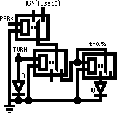
I just ordered a couple of 555 timer based time delay relays ($1.50 each) which will hold the white LEDs off long enough after each flash to stay off and let the ambers come on. The result should be that the whites won’t come back on until 1/2 second after the last amber flash. :victory:
Post by: Dazzler on December 30, 2018, 04:37:41
This thread is a bit one sided but I'm interested to see the end result.
Post by: mickd on December 31, 2018, 05:09:41
\\\ SOLVED///
... I think.
I just ordered a couple of 555 timer based time delay relays ($1.50 each) which will hold the white LEDs off long enough after each flash to stay off and let the ambers come on. The result should be that the whites won’t come back on until 1/2 second after the last amber flash. :victory:
555's, simple and reliable even at $1:50 of today's money.
Post by: The Gonz on December 31, 2018, 05:58:56
Post by: The Gonz on January 02, 2019, 06:54:34
Post by: tw2005 on January 02, 2019, 08:58:45
Post by: The Gonz on January 02, 2019, 09:26:53
Post by: tw2005 on January 02, 2019, 09:43:10
Post by: The Gonz on January 03, 2019, 04:30:33
With the current BoM running at $21.50 including the LED modules, I’m optimistic about my V1.0 and am considering adjusting the delay to 3 or so seconds to cover cranking. :winker:
Post by: tw2005 on January 03, 2019, 04:50:49
Putting it all on a single circuit board would be done better with board mounted relays, since they form the logic all by themselves. A bit of eBay trawling and I might find suitable components for a marketable V2.0.
With the current BoM running at $21.50 including the LED modules, I’m optimistic about my V1.0 and am considering adjusting the delay to 3 or so seconds to cover cranking. :winker:
:faint: